
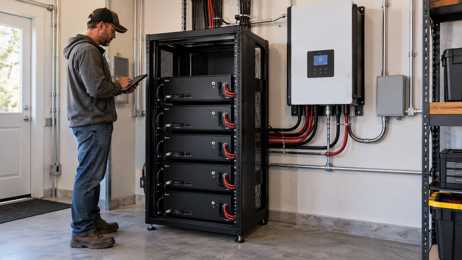
Short answer: A server rack battery is a sensible way to package modular LiFePO4 storage only when its actual DC operating window, BMS current, inverter protocol, parallel-bank configuration and installation requirements are documented for your equipment. A 48V label, a matching RJ45 connector or the presence of CAN/RS485 ports is not proof that an inverter will work with the battery. Check the electrical load and the communication handshake before evaluating price per kilowatt-hour.
This technical buying guide is focused on 48V-class rack batteries and hybrid-inverter integration in the United States—not a general guide to backing up an entire home. The WattCycle V2.5 51.2V 100Ah rack unit is a case study. Product and manual claims were checked October 13, 2026; the battery was not installed, tested or certified by GearInsightWorks.
Start by separating energy storage from power delivery
These three measurements answer different questions:
- Nominal energy (Wh or kWh): How much electrical energy the pack is rated to store, before real-world reserve settings, operating losses and aging.
- Continuous current (A): How much DC current the battery/BMS is designed to deliver or accept continuously, subject to temperature and other conditions.
- Inverter output (W or kW): How much AC output the inverter can supply under its own stated conditions. This cannot override a battery-side current ceiling.
WattCycle markets its V2.5 48V 100Ah server rack battery as a 51.2V nominal, 100Ah, 5,120Wh (5.12kWh) module with a 100A maximum continuous discharge BMS. Those are manufacturer-published specifications, not independent performance measurements. The arithmetic is 51.2V × 100Ah = 5,120Wh. WattCycle also advertises a 200A short peak for two seconds; such a brief peak must never be substituted for the continuous limit.
| Published parameter | What it means | Decision that follows |
|---|---|---|
| 51.2V nominal × 100Ah = 5.12kWh | Nameplate DC energy, not guaranteed AC output or usable runtime | Reserve SOC, inverter efficiency, actual load and temperature must still be modeled |
| 100A maximum continuous discharge | Nominal-voltage arithmetic suggests 5.12kW on the DC side before losses | Compare against inverter’s worst reasonable battery input demand, not merely its AC sticker |
| 50A standard / 100A maximum charge in bundle table | Standard operating value and absolute ceiling differ; another text field lists a different recommendation | Obtain revision-specific approved charge current and configure the inverter accordingly |
| CAN / RS485 / RS232 ports | Physical links for control/telemetry exist | Protocol dialect, baud rate, pinout, firmware and tested inverter pairing still need verification |
| 3U chassis, approximately 485 × 450 × 133mm; 91.9lb | Rack height alone does not confirm cabinet fit or handling safety | Measure depth, rails, service clearances, rack load rating and ventilation |
| Parallel expansion advertised up to 20 packs | A version-specific expansion claim, not a universal license to mix rack families | Confirm current revision, master/slave configuration, cables and BMS-bank limits |
The dimensions and weight are published in WattCycle’s rack product specifications. The manufacturer’s V2-series rack manual also describes charge/discharge limits and communication settings. Because WattCycle says V2.5 changes structure and packaging versus V2, confirm whether the shipped firmware and included manual match the version you plan to integrate.
The 6kW inverter + one 5.12kWh battery trap
Some packages put a 6kW inverter next to one nominal 5.12kWh rack module. This is not evidence that the battery can continuously run a full 6kW AC load. The official bundle specifications separately show 6kW inverter output and the battery’s 100A continuous BMS limit—and include a note that battery power is further limited by the bank, wiring and protection devices.
Illustrative engineering screen, not a measured limit: Suppose an inverter supplies a steady 6,000W AC, is 92% efficient at that operating point, and its battery is held at 51.2V. The hypothetical battery current is:
6,000W ÷ (0.92 × 51.2V) ≈ 127A DC.
That exceeds a single module’s stated 100A continuous discharge ceiling. A real battery voltage may be lower under load, making DC current higher still; the inverter may also have its own curtailment and shutdown behavior. A 100A battery might supply substantially less than the inverter’s nameplate full output on its own. Do not use this worksheet to select wire, fuses, breakers or an installed parallel count. Those decisions require the current component manuals and qualified system design.
| Hypothetical AC load | Estimated battery-side current | Against one 100A-continuous module |
|---|---|---|
| 2,000W | ~42A | Below the 100A BMS figure in this arithmetic; not a complete system approval |
| 4,000W | ~85A | Below nominal ceiling but leaves less room for real voltage sag and surge |
| 6,000W | ~127A | Above stated continuous ceiling; do not assume full battery-only output |
A second key distinction: 5.12kWh describes stored DC energy, not five hours at 1kW AC with no losses. At a hypothetical 800W AC average load and 92% inverter efficiency, ignoring reserve/aging/other losses, the theoretical energy-only limit is 5,120Wh × 0.92 ÷ 800W ≈ 5.9 hours. Reserve SOC, standby power, cold operation and the battery’s usable-voltage window shorten or otherwise change that estimate. WattCycle’s nominal-energy claim cannot validate a real-world runtime without operating evidence.
Which communication features actually matter?
CAN and RS485 identify families of electrical communication buses. They do not, by themselves, guarantee the inverter recognizes a battery’s state of charge or accepts its real-time current limits. Closed-loop communication requires a compatible protocol, compatible firmware and correctly specified physical wiring. If communications are absent, some inverters offer a documented open-loop voltage-based mode; whether that mode is permitted for a specific battery is an entirely separate question.
Victron’s DVCC documentation describes battery-provided limits such as CVL (charge-voltage limit), CCL (charge-current limit) and DCL (discharge-current limit), where supported by a managed battery. These are the types of commands that make an inverter respond to the BMS, not merely display a Bluetooth percentage. The Cerbo GX manual further distinguishes bus configuration and BMS-CAN behavior.
WattCycle lists CAN, RS485 and RS232 on the V2.5 page; its rack manual includes an LCD protocol-selection menu and connector pin information. Those details must be matched to the inverter vendor’s instructions. Victron’s BMS cable guidance cautions that the needed cable can have specific pin wiring even when connectors appear similar. Never choose a cable solely because its plug fits.
| Evidence at purchase time | Confidence level | What to do |
|---|---|---|
| Only “48V compatible” and an RJ45 jack | Insufficient | Do not order on this basis; request the actual DC range and communication profile |
| Battery advertises CAN/RS485; inverter lists generic “lithium BMS” | Still insufficient for closed-loop | Obtain supported protocol name, firmware, exact cable and control-mode steps in writing |
| Both manufacturers explicitly document the exact battery/inverter model and firmware together | Higher confidence | Confirm current revision, settings, applicable warranty and installer responsibility |
| Qualified installer has a written tested pairing and commissioning records | Stronger project-specific evidence | Verify current device labels, limits, required safety approval and follow-up support |
As checked October 13, 2026, a text search of Victron’s public battery compatibility index did not show an explicit WattCycle entry. That is not evidence that every WattCycle/Victron installation fails, nor is the index necessarily exhaustive or permanently current. It means we cannot claim an officially validated plug-and-play pairing from that particular evidence. Ask both manufacturers to identify the exact supported combination or select a specifically documented alternative.
A bounded owner-experience signal: In an August 2026 r/SolarDIY discussion about a WattLink–EcoFlow expansion cable, one participant described a battery extension that worked but did not appear as a native battery in the power-station app. That is one anecdote about a distinct EcoFlow accessory route—not a controlled test of the V2.5 rack BMS, a Victron CAN pairing or a measured reliability rate. Its practical lesson is to ask which state-of-charge and alarm data your particular connection will show; do not assume a physical energy connection equals integrated app/BMS control.
Version collision: V2, V2.5 and the parallel count
The WattCycle V2.5 product page advertises expansion to 20 batteries in parallel, and the linked V2-series manual’s parallel limit also describes 20. However, an earlier WattCycle rack introduction article and legacy listings discussed 16. Do not mix the old and new limits without checking the revision and documentation of every module you will actually install.
For illustration, four identical 5.12kWh modules total 20.48kWh nameplate (4 × 5.12) before any reserves and losses. That does not mean a bank can safely share an arbitrary 400A indefinitely: each unit’s current allocation, protective devices, cabling, BMS communication, connection symmetry and thermal environment must be engineered. Similarly, the existence of a 20-parallel claim does not mean an older revision or mixed battery brands can be daisy-chained without approval. The manual prohibits using this model as an ordinary series building block.
Rack fit is mechanical and thermal, not just “3U”
WattCycle’s cited unit is approximately 485mm wide × 450mm deep × 133mm high and 91.9lb (41.7kg), according to the product specification. “3U” references rack height; it does not verify rail support, depth clearance behind connectors, airflow or safe handling during installation. A loaded cabinet must be designed around the combined mass of every module and the structure that holds it.
The rack user manual identifies the unit as IP20, not an outdoor waterproof battery. IP20 should be treated as an indoor/protected-equipment classification; rain, condensation and washdown are not covered by a claim of water resistance. If the buyer wants storage in an exposed shed, marine compartment or mobile rack, that environment changes the product decision. Confirm approved enclosure conditions, fire separation, clearances and local permitting with the installer/AHJ rather than assuming a metal case is an outdoor rating.
Standards and product certificates: four labels that cannot be combined
Battery marketing often places several logos in one row. WattCycle lists cell-related UL 1642/UL 2580 and product/transport-related CE, FCC, UN38.3 claims in its technical marketing. Those entries do not, on their own, demonstrate that the complete installed energy-storage system has a verified UL 9540 listing. A UL 1741 claim for a bundled inverter likewise does not transfer a system certification to the batteries.
UL Solutions’ energy-storage testing overview and its code-authority explanation for pairing PV inverters with battery systems differentiate equipment/component testing from assessment of a listed ESS combination. If local code or an inspector requires a particular listing, request the actual certificate, file number, exact model combination, and scope. An unverified product badge is not a substitute for authorization by the local authority having jurisdiction.
A practical decision sequence before you pay
- Fingerprint the proposed rack module: full SKU, V2 or V2.5, current user manual, BMS firmware/version, serial range and exact data sheet. Confirm whether published charge recommendations refer to the same revision. The product’s bundle table describes 50A standard / 100A maximum charging, while other displayed specifications use different “recommended” language. Have WattCycle resolve this in writing.
- Define the DC operating envelope: battery minimum/maximum allowed voltage, charge setpoint, recommended/maximum charge amps, continuous and peak discharge conditions, under-temperature behavior and low-voltage cutoffs.
- Match the inverter precisely: model and firmware; input DC voltage, steady/surge load, efficiency behavior, charge-current settings; grid/solar coupling and AC output requirements. Use a qualified designer for load, breakers and wire protection.
- Prove the communications route: closed-loop battery profile, supported cable/pinout, BMS bus speed and handshakes, what occurs if communications fail, and whether the inverter can and should derate on CCL/DCL messages.
- Plan the cabinet and authority review: rail/depth fit, ventilation, service access, weight, environmental rating, enclosure/fire protection and inspection/permit requirements.
- Price the whole integration: batteries, rack or cabinet, inverter, communication leads, protection, labor, commissioning, documentation, future replacement/expansion and any required code upgrades.
Example poor-fit buyer: Someone with an existing Victron-controlled system who needs an officially documented, supported BMS-CAN pairing and cannot obtain a model-specific WattCycle compatibility confirmation should consider a battery on the current Victron supported/tested list, subject to the exact market model, inverter and installer approval. Someone building a separately approved integration may still evaluate WattCycle, but should not trade away documented protection behavior for a lower advertised cost per kWh.
When might the verdict change? An updated inverter manufacturer compatibility notice, an exact V2.5 pinout/protocol sheet, completed commissioning test, current UL-listed-system documentation or a revised charge-limit table could materially change suitability. Recheck documentation when these items change.
Commercial disclosure: We may earn a commission from qualifying purchases or other transactions made through links on this page.
After the inverter/BMS, installation and approval checks pass, you can review WattCycle rack batteries at the U.S. store. The link is an approved merchant-homepage destination, not a verified direct link to a particular V2.5 configuration. Verify the revision, documentation, availability and total system price before ordering.
Final rack-battery buyer record
- Battery exact SKU/revision; nominal/operating voltage; usable/nominal kWh; max/recommended charge current; continuous/peak discharge current and duration.
- Inverter exact model/firmware; battery-specific charge settings; supported BMS protocol; pinout/cable and failover behavior documented by both parties.
- Number of modules, parallel policy, matched age/type/firmware, equipment current limits and cabinet load calculations prepared by an appropriate professional.
- Required AHJ review, exact pack/system certificate where applicable; no substitution of cell or inverter certificates for full ESS listing.
- Country/region service, shipment method, warranty registration and how installer/manufacturer responsibility is assigned if either component shuts down.
Source/region note: This guide addresses technical battery/inverter selection in the U.S. using manufacturer manuals, Victron compatibility documentation and UL Solutions guidance inspected October 13, 2026. It is not a wiring diagram, commissioned design, permit determination, certificate verification or laboratory test. Always follow the exact current manuals and applicable local requirements.